Introduction
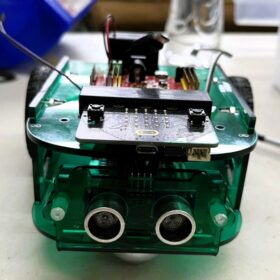
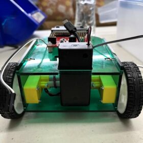
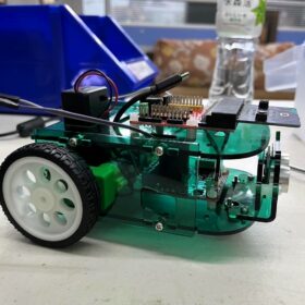
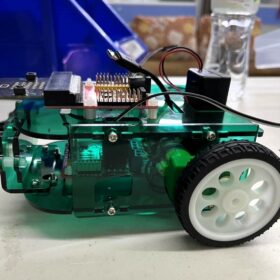
This step-by-step tutorial will guide you through assembling the RK-micro:bit robot, a differential robot chassis controlled by a micro:bit.
We will also have a separate tutorial introducing how to program this robot using MakeCode.
| author | 楊國立 (intern) | ||
| Time | 1~ 2 hours | BOM | |
| Difficulty | 3 / 5 | ||
Content
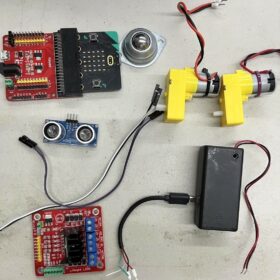
Before we begin, let’s check the materials needed for the RK-micro:bit robot:
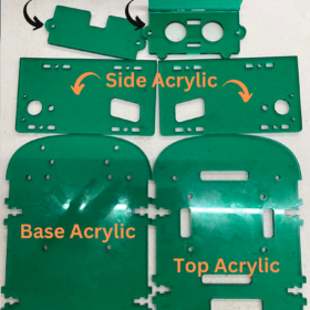
| —Micro:bit dev board * 1 —L298n motor driver module * 1 —TT Motor * 2 —Ultrasonic(HC-SR04) sensor * 1 —Ball wheel * 1 —65x15mm wheel * 2 —9VBattery Holder with On/Off switch * 1 —Micro:bit Sensor shield module * 1 —Micro USB Wire * 1 —M3*8 Screw * 2 |
—M3*12 Screw * 10 —M3 Nut * 12 —M2*20 Screw * 4 —M2 Nut * 4 —M3*6 Plastic Spacer * 10 —M3*6 Plastic Screw * 10 —M3 Plastic Nut * 10 —Acrylic sheet * 1(set) —10p Wire * 1(set) |
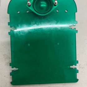
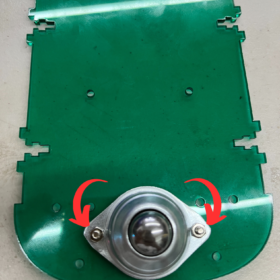
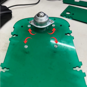
STEP 1 STEP 1: Attach the front wheel to the base board using 1 Base Board, 2 M3x8 Screws, and 2 M3 Nuts. (Either side can be attached.)
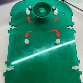
STEP 2 Attach four M3x6 screws to the base board. (Note: Ensure they are placed in the correct direction, with the screws on the same side as the ball wheel.)
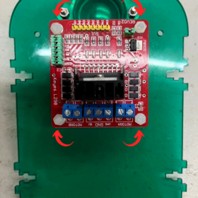
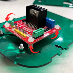
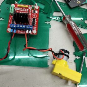
STEP 3 Mount the L298n motor driver module above the base board. (Pay attention to the module’s orientation.)
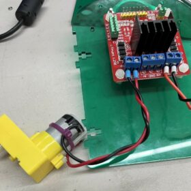
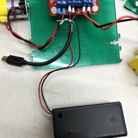
STEP 4 Connect the cables from the two motors, the 9V Battery Holder with On/Off switch, and the Micro USB Wire as follows:
- Motor B (Left): The leftmost cable is black, followed by the red cable.
- Motor A (Right): The rightmost cable is black, followed by the red cable.
- Position the USB red cables to the far left.
- Place the battery red cables to the far right.
- In the center, combine both the battery and USB black cables.
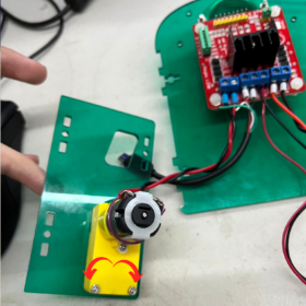
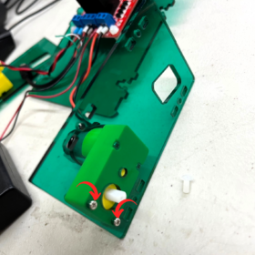
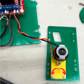
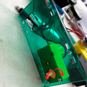
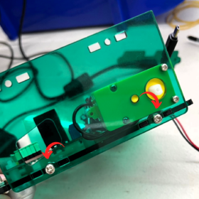
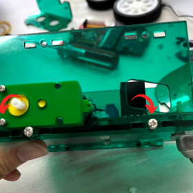
STEP 5 Attach the motors to the side acrylic panels. (Be aware of the motor’s direction and the position of the nuts.)
STEP 6 Affix the side body to the base acrylic. (Note: Do not fully tighten the screws at this stage.)
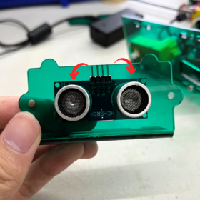
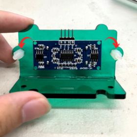
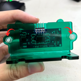
STEP 7 Mount the ultrasonic sensor onto the Ultrasonic acrylic board using two M3x6 screws.
STEP 8 Attach the ultrasonic acrylic board to the base acrylic using two M3x12 screws. (Ensure it’s attached ABOVE the base acrylic, not below.)

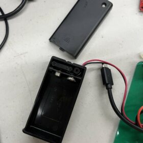
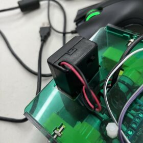
STEP 10 Position the 9V Battery Holder with On/Off switch between the top acrylic layers. (Open the battery holder first to ensure a proper fit.)
STEP 11 Route the USB cable over the top of the acrylic.

STEP 12 Connect the cables as shown in the provided pictures.

STEP 13Organize the cables over the top of the acrylic as depicted in the images.

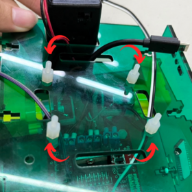
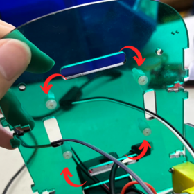
STEP 14 Secure the top board using four M3x6 screws.
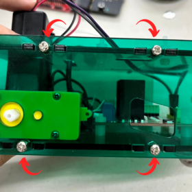
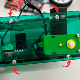
STEP 15 Attach the top acrylic to the main body and tighten all screws securely.
STEP 16 Mount the micro:bit sensor shield module on the top acrylic. (Ensure the correct orientation of the module.)

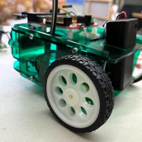
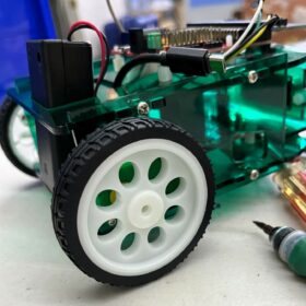
STEP 17 Attach both wheels to their respective sides.
Finished!
Feel free to adjust the settings and add your own creative touches to enhance the robot. Stay tuned for another article where we’ll demonstrate how to control this robot using the MakeCode graphical IDE.


