Why Can’t My High-Frequency Communication Device Transmit or Receive Signals?
Why Can’t My High-Frequency Communication Device Transmit or Receive Signals?
A Quick Guide to Troubleshooting Signal Connectivity Issues with Samtec solution
Sponsored by MOUSER and Samtec
Author: Sam Hsu
- Senior Engineer, Hennes Co. Ltd.
- NVIDIA Certified Instructor.
- M.S. in Electrical Engineering and Robotics, with experience designing IoT teaching projects and various IoT environment deployments.
Notice: Images 1–3 in this article were AI generated. All other images are referenced from Samtec’s official sources with Samtec’s knowledge and consent.
Why other’s Wireless Communication always Better? Any reason?
When using the latest 5G, 6G, and millimeter-wave (mmWave) development boards, do you often encounter problems such as devices failing to connect, packet loss, or being unable to send messages to servers or receivers? Moreover, when two systems use the same chip or module but deliver dramatically different performance, many people first may wonder whether the cause is from the chip or software. However, the key issue is often hidden in the details — the importance of internal cables and connectors.
In high-frequency communications (GHz-level and above), signal wavelengths are extremely short. Even small amounts of cable attenuation, connector impedance mismatch, or physical deformation caused by bending can severely weaken the signal or disrupt its phase before it reaches the antenna. Therefore, selecting high-quality, highly matched internal RF cables and solderless/precision connectors is an often-overlooked foundation for maintaining stable signal performance.
In this article, we will start with the basics and walk through a practical troubleshooting process for high-frequency communication problems. We will look at common issues across the RF physical layer, power integrity, clock accuracy, EMI, and environmental conditions, before focusing on one of the most overlooked factors: high-frequency cables and connectors.
We will also explore how key parameters such as impedance matching, phase stability, insertion loss, temperature stability, shielding effectiveness, and bend radius affect signal integrity. Along the way, we will introduce Samtec solutions designed for demanding high-frequency applications, helping engineers identify problems faster and build more stable and reliable communication systems.
Troubleshooting Checklist: Common Communication and Transmission Issues During Application Development
Before checking the cables, first confirm whether the hardware or environment is experiencing any of the following common abnormalities:
1. Hardware and RF Physical-Layer Issues:
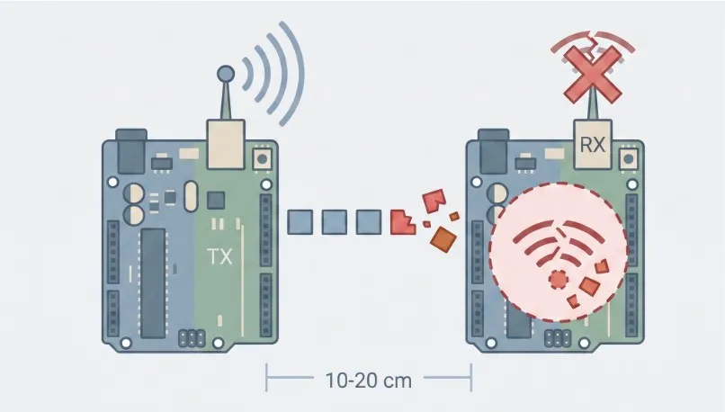
Issue 1: The Transmitter and Receiver Are Placed too Close and Cannot Communicate Properly:
When two development boards are only 10–20 cm apart, the packet loss rate may be extremely high or packets may not be received at all. After increasing the distance to 1–2 meters, communication returns to normal.
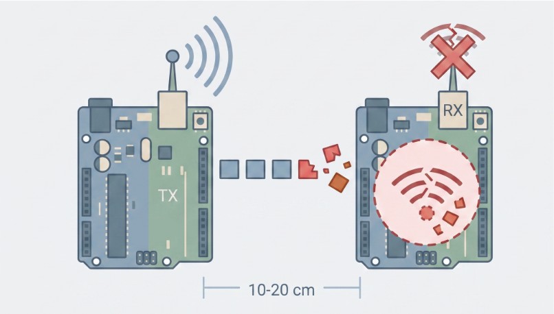
Fig. 1. placement issues (AI generated illustration)
Issue 2: The Chip Restarts or Packets Are Interrupted at the Moment of Transmission.
The chip operates normally in RX (receive) mode. However, once it switches to TX (transmit) mode to send data, the module immediately restarts or the RF signal is interrupted.
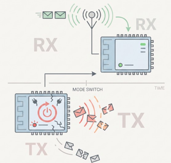
Fig. 2. mode switch issues (AI generated illustration)
High-frequency TX operation requires a very high peak current. When the low-voltage load current or input voltage of the development board changes suddenly, a voltage regulator with slow response may cause signal interruption or module resets. Insufficient decoupling capacitance or traces that are too narrow on the PCB can also cause the instantaneous voltage to drop below the minimum operating-voltage threshold of the chip.
Issue 3: Boards Communicate Normally at Room Temperature but Fail Completely under Temperature Extremes or Across Different Batches.
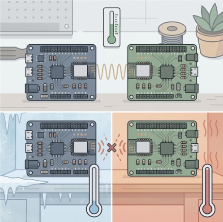
Fig. 3. temperature issues (AI generated illustration)
High-frequency communication places extremely strict accuracy requirements on the chip clock signal (main crystal oscillator), such as ±10 to ±20 ppm. If the load capacitance (CL) is not properly matched or temperature drift is too large, the carrier frequency may shift outside the RX bandwidth of the receiver, making the signal impossible to capture.
2. Electromagnetic Interference (EMI) and Environmental Issues:
Issue 1: Receiver Performance Degrades After Connecting the Main Controller Board:
The RF module works normally when powered independently. However, once it is connected to a main controller board such as an ESP32, STM32, or Raspberry Pi, receiver sensitivity decreased dramatically.
The possible causes may include:
Noise from the DC-DC switching power supply, high-speed SPI/SDIO traces, USB 3.0 interfaces, or MCU clock signals on the main controller board may not be adequately shielded or isolated by the ground plane. This noise can couple through space into the antenna or the LNA input.
Issue 2: Strong Co-Channel Interference and the Shielding Effect:
Signals frequently drop out when testing in an office but work normally after moving to an outdoor area, or the packet loss rate becomes extremely high during certain time periods.
For example, in the 2.4 GHz band, strong Wi-Fi signals can cause interference. Walkie-talkies and industrial motors can also generate broadband electromagnetic noise. In mmWave development, a board may communicate normally when placed on a desk, yet lose the connection when a person walks in front of it or when it is placed inside a metal enclosure.
In addition to the situations above, one of the most frequently overlooked issues in high-frequency communication is the selection of high-frequency RF cables and connectors.
Before discussing cable specifications, we first need to understand one of the most fundamental concepts in high-frequency communication: phase.
What Is “Phase”?
A high-frequency signal is essentially an electromagnetic wave, much like waves rising and falling on the sea or the beat of a metronome in music, with peaks and troughs.
- Phase: Describes where a wave is in its cycle at a given moment — essentially, “what part of the beat is it on?”
- If two signals move perfectly in step, with peak aligned to peak, they are said to be “in phase.”
- If one signal lags behind the other (i.e. half a cycle), with a peak aligned to a trough, a “phase difference” occurs.
What Happens with Phase Drift?
Ideally, the propagation time and timing of a signal through a cable should remain completely stable. However, if a cable is bent, pulled, or exposed to temperature changes, it may bring a few micrometers in the cable’s physical length or dielectric structure, which can cause undesirable “phase drift” — the timing gets out of step. This can lead to the following serious problems:
- Beam Misalignment (Antenna Divergence/Shift): 5G and mmWave antennas use beamforming technology to combine highly directional signals by using multiple cables to provide extremely precise phase control. If a cable introduces 20°–30° of phase drift, the beam may experience beam squint or spread out, causing antenna gain to drop significantly (by 3–10 dB) and making it impossible for the device to find the base station.
- Signal Decoding Failure and a Sharp Drop in Data Rate: Advanced communication modulation schemes such as QAM encode information in both the amplitude and phase of the signal. If the phase drifts unexpectedly, the receiver may interpret a 1 as a 0 (degraded EVM), resulting in heavy packet loss and retransmissions. The data rate may collapse or the connection may time out.
- Ghost Targets and Errors in Automotive Radar Range and Angle Measurements: mmWave radar determines target position by calculating phase changes in reflected waves. Phase drift caused by cable movement may cause the radar to calculate a target 10 meters away as being 12 meters away, or generate virtual targets that do not exist in the point cloud (ghost targets).
Why Does Bending a Cable Disrupt High-Frequency Microwave/mmWave Data?
In the microwave (3 GHz–30 GHz) and mmWave (30 GHz–100+ GHz) bands, signal wavelengths are extremely short (mmWave wavelengths are only 1–10 mm). Even slight physical bending of a conventional coaxial cable can compress the internal dielectric and shift the center conductor off-axis, causing severe phase and amplitude distortion.
For example:
- Microwave Band (3 GHz–18 GHz): Bending angles ≥40°–90°: With a conventional cable bent by 90°, the phase shift can typically reach 10°–30° or more.
- mmWave Band (30 GHz–60+ GHz): A bending angle of only about 15°–30° or more can be significant. At 28 GHz or 60 GHz, a physical length change of only 0.1 mm can produce more than 20°–40° of phase shift.
Key Specifications for Selecting High-Frequency Cables and Connectors
In high-frequency and high-signal-integrity applications such as microwave and mmWave systems, the goal of cable selection is to ensure stable phase, smooth amplitude behavior without abrupt attenuation, waveform fidelity, and immunity to external interference. Pay particular attention to the following key specifications:
For the high-frequency cable example in this article, data from Samtec NITROWAVE cables is used for illustration.
1. Electrical Performance Specifications (Core Factors for Signal Integrity)
- Impedance Matching and VSWR / Return Loss
- Key point: The characteristic impedance of the cable (typically 50 ohms in RF systems) must remain highly uniform throughout the entire cable. When selecting a cable, pay attention to voltage standing wave ratio (VSWR) and return loss.
- How it prevents signal deviation: A low VSWR (such as 1.2–1.4) reduces repeated reflections at interfaces and inside the cable, preventing waveform ripple and inter-symbol interference (ISI).
As shown in the figure below, when a Samtec 2.92 mm solderless compression connector is connected to a PCB stripline, the measured VSWR curve from DC to 40 GHz remains extremely low (with a maximum of only about 1.14), indicating that reflected-wave is carrying a very small energy.
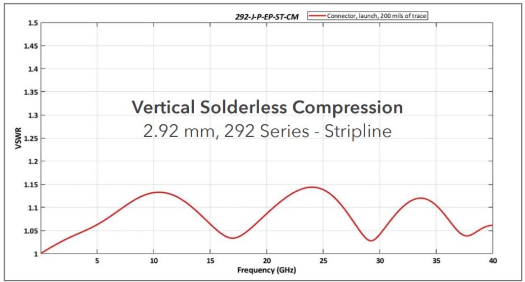
Fig. 4. The VSWR measurement used AFR
- Phase Stability with Flexure
- Key point: High frequencies, especially from >18 GHz to 110 GHz, are extremely sensitive to changes in physical length. Choose cables specified as “phase stable” and pay attention to phase variation during bending (for example, within ±5°–10°).
- How it prevents signal deviation: Cables featuring a Dynamic Performance Layer (DPL) or interlayer construction — for example, multilayer spiral metal foil and braided shielding structures — can absorb internal stress during bending and prevent phase drift caused by the center conductor moving off-axis.
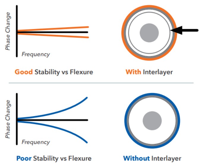
Fig. 5. Good Stability vs. Flexure
- Amplitude Stability and Insertion Loss
- Key point: Pay attention to the maximum insertion loss per meter (dB/m) at the target frequency, as well as the amplitude variation during bending (typically controlled within ±0.1 dB).
- How it prevents signal deviation: Low-loss dielectric materials such as expanded polytetrafluoroethylene (ePTFE) reduce dielectric loss, which can increase sharply as frequency rises, helping maintain the expected signal level and SNR at the receiver.
As shown in the figure below, the measured Natural 90° Forward Bend and Reverse 90° Bend traces extend all the way to 71 GHz with only small amplitude fluctuations, remaining close to the 0.0 dB axis and within the 0.1 dB limit.
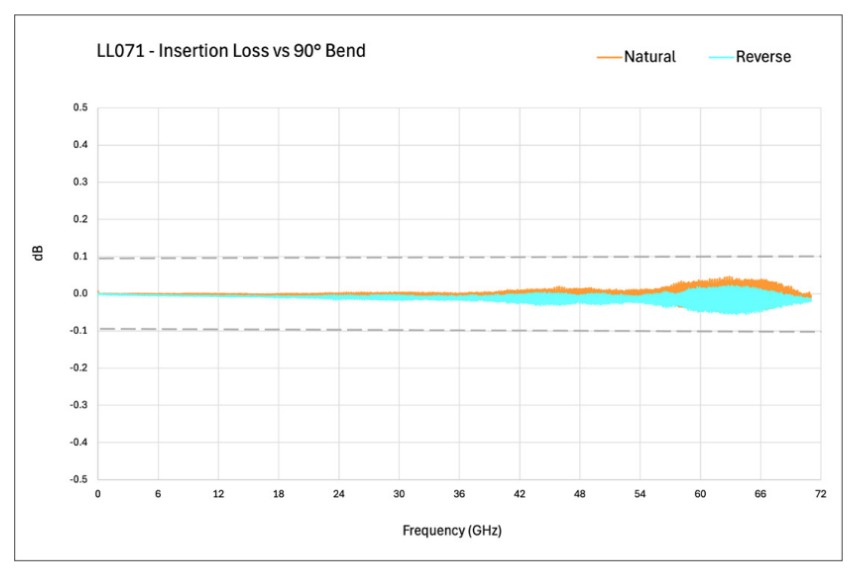
Fig. 6. LL071 – Insertion Loss vs. 90° Bend
- Phase vs. Temperature
- Key point: Conventional PTFE dielectric materials exhibit a phase knee in the 18°C–25°C room-temperature range, which can cause a large phase jump when the temperature changes slightly.
- How it prevents signal deviation: Select dielectric materials optimized for temperature stability (Phase Track / Low Phase Change vs. Temp.) to ensure that testing and data transmission remain free from timing errors across different operating temperatures.
As shown in the figure below, the PTFE phase knee affects the phase of high-frequency signals in the room-temperature range. From 10°C to 25°C, a 15°C temperature difference produces a phase change of more than 1350 ppm.
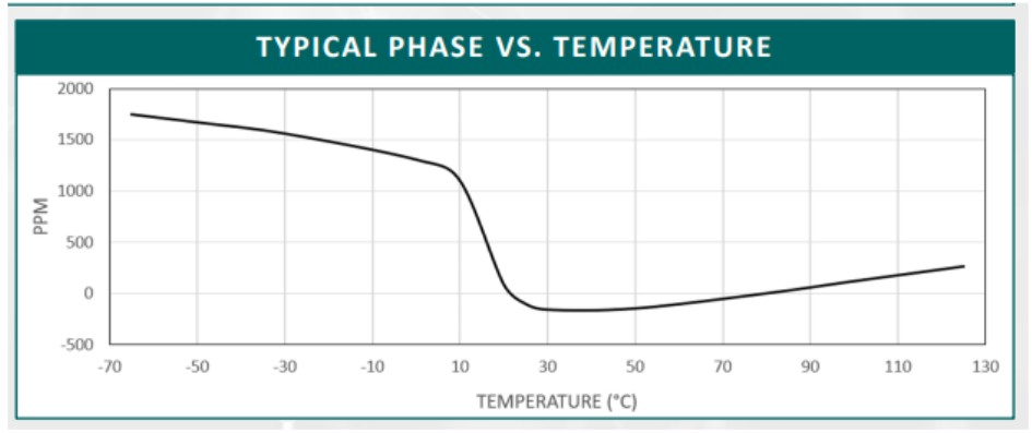
Fig. 7. The relationship between typical phase and temperature
- Shielding Effectiveness
- Key point: Shielding effectiveness should generally reach -90 dB to -100 dB or better.
- How it prevents signal deviation: High shielding effectiveness — using double braided shielding, double metal foil, or dual-layer constructions — can block external EMI noise from coupling into the cable while also reducing crosstalk when multiple cables are routed in parallel.
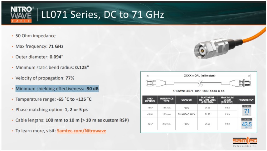
Fig. 8. Minimum shielding effectiveness: -90 dB
2. Mechanical and Structural Specifications (The Physical Foundation for Long-Term Stability)
- Minimum Bend Radius
- Key point: Distinguish between the static bend radius and the dynamic flex radius.
- How it prevents signal deviation: If the cable is routed below its permitted minimum bend radius (for example, the static bend radius of miniature cables such as LL071/LL095 is typically about 0.125–0.25 inches), the internal dielectric may be permanently compressed or deformed, resulting in impedance discontinuities and signal distortion.
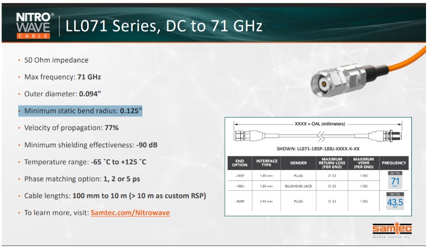
Fig. 9. Minimum static bend radius: 0.125”
- Jacket Material and Armor
- Key point: Choose the jacket material based on the operating environment, such as a wear- and temperature-resistant FEP jacket, or add a metal armor layer for protection.
- How it prevents signal deviation: In production-line testing, robotic arms, or aerospace environments, armored cables can prevent damage to the internal precision RF structure caused by stepping, twisting, pulling, or crushing.
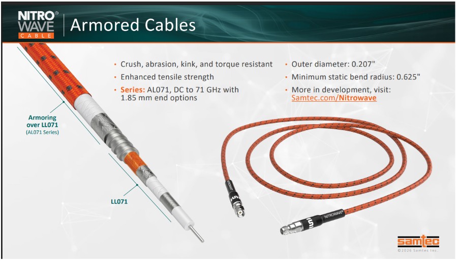
Fig. 10. NITRO® WAVE Armored Cables
Conclusion
When a high-frequency communication device experiences signal loss or unstable connectivity, do not only check the power supply and chip register settings. Re-examine the quality of the internal cables and connectors. Understanding the effects of flexure-related phase stability, insertion loss, and phase drift — and selecting suitable precision RF cables — can save a significant amount of time when troubleshooting high-frequency applications.
While recommending Samtec as one of the high-quality solution providers, we hope the troubleshooting guidance and cable-material selection considerations above will help you quickly identify and eliminate communication problems during application development.
Samtec Reference Materials:
本文發表於科技趨勢與新知。
留言 💬 (0)
還沒有留言,來當第一個。