[授權翻譯] NXT/EV3 Arduino I2C 終極指南 – 感謝Muhannad Al-Khodari

NXT/EV3 Arduino I2C 終極指南

註:本文經原作者 Muhannad Al-Khodari 同意 CAVEDU 翻譯成正體中文後用於教學推廣,歡迎註明出處後轉載。感謝CAVEDU實習生與台大自造者社長張德芯同學協助翻譯

本文將介紹如何連接LEGO EV3或NXT系列與Arduino UNO。過去幾年,筆者都是使用LEGO Mindstorms提供的圖形化程式與RobotC來控制NXT 和 EV3,但總覺得有些馬達、感應器會受到積木本身的限制,或是希望能擴充一些積木不支援的功能。本文將會告訴您如何按部就班地掌握解決上述問題。未來會再增加 LabVIEW 的做法。

在繼續深入前,請注意這不是”五分鐘掌握NXT/EV3與Arduino的I2C”,您需要投入一些時間,大約2~3天閱讀、消化並測試,之後才能應用到自己的專案上。當然也與耐心和投入的時間有關。

簡介

說實話,這篇指南是從其他較基礎的指南衍伸出來的。最早的兩篇可能也是網路上最先出現關於連接 NXT或EV3與Arduino Uno的文章,是由Dexter Industries 所撰寫,非常適合作為入門的起點,但在專案應用上可能稍嫌不足。本文中引用的部分將會以 [DI] ….. [/DI]標註。第三篇參考是由 Justin Eng撰寫,他還是一個大學生,以Dexter Industries的指南為基礎去製作專案並在部落格上分享。本文中引用的部分將以[JE] ….. [/JE]標註。

接下來才是正文,其中包含了其他指南的摘要,並加上了我個人的補充。最後一件事,在Dexter Industries 的指南中使用的是Arduino Uno,但他們提到其他Arduino 開發板也可以使用,但在我測試過Arduino Mega 2560後,我認為這個資訊不太對,本文會有一段來說明這個問題。

I2C通訊協定

這個段落是針對想徹底理解NXT/EV3 與Arduino Uno之間如何通訊的人所寫,沒興趣的人可以跳過,但建議至少看一下圖後面的最後一段。

[引用自Dexter Industries]NXT/EV3和 Arduino 可以透過I2C通訊,本教學中將設定Arduino為I2C 從方(slave),NXT/EV3為I2C主方(master)。其中NXT/EV3 必須是主方。雖然超出本篇範圍,但Arduino是有辦法作為主方操控 NXT/EV3 的。

為什麼是I2C呢?簡而言之,這是NXT/EV3除了藍牙以外有支援的通訊方式(使用藍牙的話會有很多問題。可以在Justin Eng部落格中找到詳細的說明)

http://nxtarduino.blogspot.com.es/2013/12/week-1-system-overview-aka-it-begins.html

http://nxtarduino.blogspot.com.es/2013/12/week-2-functional-requirements-for.html

I2C背景知識:

[引用自 Justin Eng] I2C是一種嵌入式電子元件間的通訊協定。硬體端指定一個雙線系統,由SDA (序列資料)和 SCL (序列時脈)組成,兩者皆會被拉高到所需的邏輯電位。所有裝置都要連上這兩條線,通訊會在特定的主方裝置開始發出訊號時發生。只有主方(master)可以送出訊號,從方(slave)只能被動的接收訊號。

I2C

在一個匯流中可以有多個從方,每一個從方必須有各自的位址,當主方送訊號到從方時,訊號會被發到匯流中。訊號的標題會包含從方位址。所有從方都會收到這個訊息,但只有位址符合的從方會讀取訊息中的數據。因此我們在同一個NXT/EV3可以連接多個Arduino,Arduino可以連接多個感應器與馬達。筆者曾經成功的將NXT與兩個Arduino相連,最多可以連接128個,從方位址通常是16進位(0x01, 0x0A)

硬體部分

1.  簡單但是比較貴的方法
購買 DI的麵包板轉接頭Dexter Industries Breadboard Adapter for the LEGO MINDSTORMS NXT(圖片摘自 Dexter Industries Guide)。

socket

2.  比較難的方法幾乎不用花錢
購買兩個 82KΩ 電阻,並且鼓起勇氣,剪斷一條LEGO Mindstorms的連接線,好處是可以獲得兩條轉接線。連接線可以再買,建議將連接線和上排針(圖片摘自 the Justin Eng Guide)。
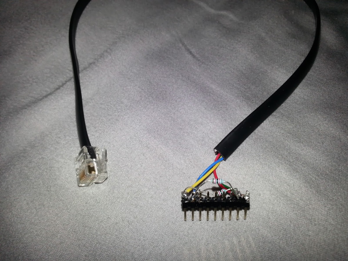
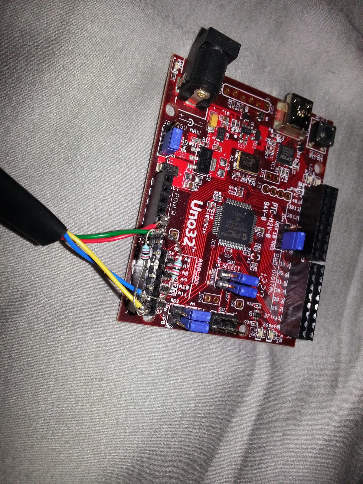
wires1

wires2
下面是線路示意圖(圖片摘自the Dexter Industries Guide):

wires3

如果使用了DI的轉接板,上拉電阻已經內建在板子上,只需要透過跳線連接即可。

電路提供了必要的電源給Arduino,但注意NXT/EV3的電流不要太大(建議不超過50 mA),如果Arduino與PC有透過USB 連著或是有其他外接電源,則不需要連接Vin的綠線,但是 GND還是要接地。

確定Arduino與sensor port 1是連接著的,雖然不知道原因,但是其他port似乎不能正常執行I2C,雖然所有 LEGO Mindstorms感應器使用 I2C 去與NXT/EV3 積木溝通。

軟體部分

這是教學文中最重要的一部分,不論你是用NXT還是EV3,RobotC或是LEGO Mindstorms 圖形化程式,Arduino的程式都是相同的。為了可以順利了解下面這一段落,我建議你可以再開始前先暖身一下。

RobotC或LabVIEW的使用者,請閱讀下面這篇:
http://www.dexterindustries.com/howto/connect-the-arduino-and-the-lego-mindstorms-together/

使用EV3 圖形化程式的人請先閱讀這篇:http://www.dexterindustries.com/howto/connecting-ev3-arduino/

程式碼概述

看完DI的基礎指南,並且跑過指南提供的程式碼後,應該會出現一些問題,現在我們就要來解決。我們想要製作一些進階的程式block,現在我會開始利用EV3圖形化程式介面解釋,因為利用block會比較容易理解。後面我會延伸到RobotC,請務必閱讀下個段落(不論你使用哪種程式語言),因為基本的概念都是相同的。如果有不懂的部分可以跳過,後面可以在RobotC的段落中找到相應的部分。

EV3圖形化程式

如同 Dexter Industries’ guide中提到,他們的I2Cblock提供下列的功能

·         Write 1 Byte: 寫入一位元到Arduino

·         Read 1 Byte: 從Arduino讀取一位元

·         Write 8 Bytes: 寫入八位元到Arduino

·         Read 8 Bytes: 從Arduino讀取八位元

·         Read 8 Bytes ASCII: 以字串形式從Arduino讀取八位元,這個block還需要再修正一下,因為讀到的是一個單字而不是一個字串,可以利用“My Block Builder”建立block。

read string

·         Analog Read:可讀取Arduino類比輸入腳位的值

·         Digital Write:可寫入Arduino數位腳位的狀態

你必須在每一個訊息後加一個 等待50ms的block,才能確保每一個訊息有被接收與處理。

根據Dexter Industries的指南,每一個block有不同的Arduino程式,It’s very crazy!!!所以你才需要利用基本的I2C block建立新的block,這樣就只需要一種arduino的code,總而言之我們會需要下列4種block:

·         Move Arduino Servo Motor( Arduino_Address, motor_pin, angle )

·         Move Arduino DC Motor (Arduino_Address, motor_pin, speed )

·         Set Arduino LED (Arduino_Address, LED_pin, state )

·         Read Arduino Sensor (Arduino_Address, sensor_pin, analog/digital )

你可以依據專案需求增加需要的block,例如讀取案件的狀態或是透過螢幕顯示數值等等。

在此我想補充一點,使用這些block控制EV3積木時,我們無法讀取或寫入一個完整的位元,只能送出或收到0~127之間的值,Don’t ask me why!!

終於,好玩的要開始了!

使用(Write 8 Bytes) 的block 並且把所有指南中的參數編碼成既定的格式。範例如下:Write_8_Bytes( Arduino_Address, Device_code, pin_num, special_value , optional_byte1, optional_byte2 , 0 , 0 ,0 )

·         Arduino_Address: 我們想要通訊的Arduino從方位址

·         Device_code: 將數字設定為 (1: led, 2: servo_motor, 3: dc_motor, 4: sensor). 可以隨喜好增加

·         Pin_num: 這個參數有兩種使用方式,第一種是直接選擇一個要連接的腳位,第二種是把它當作裝置的編號。假設你的專案有五個馬達、三個LED、三個感應器都要與Arduino相連。也許你還沒決定好腳位,並且測試中可能會再調整,我們可以用“Move motor number 2”或”Read sensor number 3” 然後在Arduino Code對應到相對的腳位。

·         Special_value: 這個值會依不同裝置而不同( servo_motor -> angle, dc_motor -> speed,  led -> state, sensor -> analog/digital ),對感應器而言,可以不用只用這個值如果我們將pin_num當作device number,後面會在其他章節進行討論。

Note: 要在 “My Block” 上使用arduino圖案的話,必須將“Icons” 資料夾複製到指定路徑。

使用教育版的人:C:\Program Files\LEGO Software\LEGO MINDSTORMS Edu EV3\Resources\MyBlocks\images
使用家用版的人:C:\Program Files\LEGO Software\LEGO MINDSTORMS EV3 Home Edition\Resources\MyBlocks\images

下面是各個block的說明:

·                Set Arduino LED (Arduino_Address, LED_pin, state ) ->
Write_8_Bytes( Arduino_Address, 1, pin_num, state ,0 ,0 ,0 ,0 ,0 )
這很容易,狀態的參數會是true/false (1/0) 對於不熟悉EV3圖形化程式的朋友:

上面淺藍色的block就是一個程式語言中的一個函式,由一些基礎的block組成
下面一串block為函式本身,灰色block 決定了參數,如果右端又第二個灰色block則為函式的輸出 。

LED
·                Move Arduino Servo Motor( Arduino_Address, motor_pin, angle ) ->
Write_8_Bytes( Arduino_Address, 2, pin_num, angle ,0 ,0 ,0 ,0 ,0 )
可惜的是因為EV3只允許127以下的值,所以馬達無法回應更大的角度,但是別擔心,我有辦法!既然角度值在一般的伺服馬達上是±1 度,我們可以送出角度值/2,這樣就算實際角度值是100 度,我們送出50,然後在Arduino code 中再乘以二。這表示[0,180] 會以[0,90]的形式送出(比127小),但是有時候會喪失一度的精度。(如果你希望馬達轉51度,但是51/2= 25,所以馬達會轉50 )如果你的專案需要很高的精確度,當角度值是奇數時你會需要使用另一個位元去標示( real_value = sent_value + 1 )

所以最終版會是:Write_8_Bytes( Arduino_Address, 2, pin_num, angle/2 , angle%2 ,0 ,0 ,0 ,0 ) // %: modulo
// 50%2 = 0 , 51%2 = 1

第二個紅色方塊會把輸入值無條件捨去成整數 (51.5 變成51).

·         Move Arduino DC Motor (Arduino_Address, motor_pin1, motor_pin2 , speed ) ->
Write_8_Bytes( Arduino_Address, 3, pin1_num, speed1 , pin2_num , speed2 ,0 ,0 ,0 )

直流馬達需要兩個PWM腳位,所以要送出兩個腳位的編號。馬達正轉時,我們必須將速度值送到第一個腳位,並且第二個腳位要寫入0,反之亦然。LEGO 的馬達速度最大為100,我們就沿用這個範圍,但是在Arduino code 需要乘以2.55倍因為直流馬達速度的最大值為255。

dc.png

·         Read Arduino Sensor (Arduino_Address, sensor_pin, digital\analog ) ->
Write_8_Bytes( Arduino_Address, 4, pin_num, analog/digital ,0 ,0 ,0 ,0 ,0 )
Read_1_Byte ( Arduino_address, [output] value )
analog/digital的值會是 true/false (1/0),它表示感應器是不是有連接到對應的腳位


這邊是一個範例,假設你有一台車,有兩個輪子連接直流馬達,第三個平衡用的輪子,一個伺服馬達控制超音波感應器和一個LED指示燈。

robot
這個機器人的目標是避障,程式碼如下:

Loop Start

Set servo to 90 degrees

Wait 1 second

If ( ultrasonic_value > 25 )

                Move forward

Else

                Stop the robot

                Turn LED on

                Set servo to 45 degrees

                Wait 1 second

                X = ultrasonic_value

                Set servo to 135 degrees

                Wait 1 second

                Y = ultrasonic_value

                If ( X > Y )

                                Turn to the right a little

                Else

                                Turn to the left a little

                Turn LED off

Loop End

硬體連接如下:

  • DC motor 1 pins: 5,6
  • DC motor 2 pins: 9,10
  • Servo motor pin: 11
  • LED motor pin: 2
  • Ultrasonic Sensor pin: A0

robot_prg

實際上大部分的超音波感應模組需要兩個數位腳位,但現在假設這樣是可以用的,後面arduino code會再進行討論。

EV3圖形化程式到這邊告一段落,提供給大家下載的檔案中會有Dexter Industries’ 的I2C block、我製作的Arduino blocks 和前面的範例。

首先打開EV3程式,匯入Dexter Industries的I2C block,然後打開i2c.ev3 project file(內建I2C custom block),就可以開始寫你自己的程式。

你可以選擇跳過下個RobotC段落直接去看Arduino程式碼的部分


RobotC 程式碼

如同 Dexter Industries指南提到的,這並不容易,我們將會使用和EV3 圖形化程式相同的做法,請閱讀下方的程式碼,程式碼後面會有說明。

wp-1455150184370.png

·         I2C 基礎

1.      RobotC中,從方位址一定會平移一個bit, 因為從方位址有7 個bits 長,bit 0..bit 6 (從0…127).
但是當收到從方的位址時, 有的環境會使用 8 bits

也又是說
bit 0 = 0 => 讀取從方
bit 0 = 1 => 寫入從方
bits 1-7 :位址 從 0…127
如你所見,位址從bit 0-6 平移到 1-7.
RobotC 和Lego NXT 使用 8 bits coding, 但是 EV3 和 Arduino 使用7-bit位址coding.
以上是Helmut Wunder提供的解釋

2.      RobotC I2C 中的位元是 0~255

3.     主/從方之間的通訊預設為send 與 request,不需要進行“write” 和“read”

4.      “return_size”代表訊息中向從方要求回覆的位元數,如果不需要從方回覆時可以設定為0

5.      “message_size” 代表要發給從方“data”的位元數,在”i2c_msg” 函數中,我們把 message_size+3,這 3 byte就是訊息的標頭,分別是 (slave_address, message_size, return_size )

6.      data bytes是5 個位元,你可以隨意編碼,最後一個位元必須小於99。我不確定為什麼是5個位元,以及最大值為什麼是99,但是這是我多次嘗試的結果。

·         裝置函數(這部分和EV3_GP非常相似

·         set_light( address, pin_num , state) ->
i2c_msg(address, 2, 0, 1, pin_num, state, 0, 0)
message_size 是2 因為我們只有送出 pin_num 和 state
return_size是 0 因為設定狀態不需要回覆

byte0 是 1因為是device_code.

·         set_servo_motor( address, pin_num, angle) ->
i2c_msg(address, 3, 0, 2, port, angle, 0, 0)
message_size 是 2 因為只送出 pin_num 和 angle
return_size 是 0 因為設定角度不需要回覆
byte0是 2 因為是device_code

注意這邊不需要送出angle/2 或是 angle%2,因為RobotC中我們可以送出0~255的值

·         set_dc_motor( address, pin1_num, pin2_num, speed) ->
i2c_msg(address, 3, 0, 3, pin1_num, speed1, pin2_num, speed2)
message_size 是 4 因為我們要送出兩個pin_num、speed還有 sign
return_size 是 0 因為不需要回覆
byte0 為 3 因為是 device_code

如同EV3_GP,我們希望速度值的範圍是-100~100,因為RobotC的環境下I2C訊息中最後一個位元不能超過99,所以99為最大值

·         read_sensor(address, pin_num, analog_digital) ->
i2c_msg(address, 2, 1, 4, pin_num, analog_digital , 0, 0)
message_size是2因為我們送出 pin_num 和 analog_digital

return_size是 1 因為我們讀到一個感應器的值,我們需要送回一個回覆

byte0是4 因為是device_code

注意我們在送出與與收到訊號時使用同樣的指令,不像EV3圖形化程式 。

3.      範例:
範例和前一段落相同,下載的檔案中有一個 “i2c_robot_C.c”,可以直接打開來調整後使用

LabView :

未來會再擴充這部分,如果你有看懂EV3圖形化程式的段落,搭配Dexter Industries的說明相信你也可以自己完成這部分。
http://www.dexterindustries.com/howto/connect-the-arduino-and-the-lego-mindstorms-together/

Arduino 程式:

既然現在你熟悉了I2C 通訊的原理以及”編碼”的概念,你一定很想知道Arduino從方的程式要如何處理,從方常常是中斷驅動(interruption-driven),主方送出訊息然後從方處理後視情況回覆。當收到訊息時,從方需要解碼(decode) 並且執行主方的要求,我們將這些位元存在一個陣列中(instruction array),並且”instruction”。當一個I2C 訊息被收到後,從方呼叫收訊對應的函式(onReceive) ,並且如果這個訊息需要回覆,從方呼叫回覆對應的函式(onRequest)。下面的程式碼是寫給會寫arduino程式的朋友看的,如果不會的話,請你學會再回來看。

// I2C Slave Send / Receive

// How to send data from the LEGO Mindstorms NXT/EV3 to the Arduino.
// For LEGO Mindstorms
// Demonstrates how to connect a LEGO MINDSTORMS to an Arduino and Send commands,
// receive data.
// A4 – SDA
// A5 – SCL
// See www.dexterindustries.com/howto for more information on the physical setup.
//________________________________________________________________________________
//________________________________________________________________________________
//________________________________________________________________________________

#include<Wire.h> // I2C library
#include <Servo.h>

///----------------------------------------------
///----------------------------------------------

int instruction[5] = {5,0,0,0,0};

/// instruction[0] = 1 (LED), 2 (servo motor} ,3 (DC motor), 4 (sensor)
///
///
/// instruction [0] = 1 ==> instruction [1] is port (LED digital pin)
/// instruction [2] is: 0 (LED off) or 1 (LED on)
///
/// instruction [0] = 2 ==> instruction [1] is port (servo motor number)
/// instruction [2] is angle
///
/// instruction [0] = 3 ==> instruction [1] is pin1 number
/// instruction [2] is pin1 speed (0-99)
/// instruction [3] is pin2 number
/// instruction [4] is pin2 speed (0-99)
///
/// instruction [0] = 4 ==> instruction [1] is pin number
/// instruction [2] is: 0 (analog pin) or 1 (digital pin)
///

//________________________________________________________________________________
//________________________________________________________________________________
//________________________________________________________________________________

Servo temp_servo;
int temp_sensor = 0;

void setup()
{
Wire.begin(0x04); // set the slave address
Wire.onRequest(requestEvent); // Sending information back to the NXT/EV3
Wire.onReceive(receiveI2C); // Receiving information!

// Debugging
Serial.begin(9600);

}
//________________________________________________________________________________
void loop()
{
delay(500);
}

//________________________________________________________________________________
//________________________________________________________________________________
//________________________________________________________________________________

byte read_byte = 0x00;
int byte_count = 0;


// When data is received from NXT/EV3, this function is called.
void receiveI2C(int bytesIn)
{
read_byte = bytesIn;
byte_count = 0;
while(1 < Wire.available()) // loop through all but the last
{
read_byte = Wire.read();

instruction[byte_count] = read_byte;

byte_count++;
}
int x = Wire.read();
// Read the last dummy byte (has no meaning, but must read it)


if( instruction[0] == 1 )
{
Serial.println(" Light ");

Serial.print("Pin: ");
Serial.println(instruction[1]);
pinMode(instruction[1], OUTPUT);

Serial.print("State: ");
if(instruction[2] == 0)
{
Serial.print("off");
digitalWrite(instruction[1], LOW);
}
else
{
Serial.println("on");
digitalWrite(instruction[1], HIGH);
}


}
else if( instruction[0] == 2 )
{
Serial.println(" Servo Motor ");

Serial.print("Pin: ");
Serial.println(instruction[1]);
temp_servo.attach(instruction[1]);


//Uncomment the next line if you are using EV3 Graphical Programming
//instruction[2] = instruction[2]*2 + instruction[3];

Serial.print("Angle: ");
Serial.println(instruction[2]);
temp_servo.write(instruction[2]);

}
else if( instruction[0] == 3 )
{
Serial.println(" DC Motor ");

Serial.print("Pin1: ");
Serial.print(instruction[1]);
pinMode(instruction[1], OUTPUT);

Serial.print(" Speed1: ");
Serial.println(instruction[2]);
analogWrite(instruction[1], instruction[2]*2.55);

Serial.print("Pin2: ");
Serial.print(instruction[3]);
pinMode(instruction[3], OUTPUT);

Serial.print(" Speed2: ");
Serial.println(instruction[4]);
analogWrite(instruction[3], instruction[4]*2.55);

Serial.print("Result movement: ");
if (instruction[2] !=0)
Serial.println("Forward");
else
Serial.println("Backwards");
}
else if( instruction[0] == 4 )
{
Serial.println(" Sensor ");

Serial.print("Pin: ");
Serial.print(instruction[1]);

if ( instruction[2] == true )
{
Serial.println("Analog");

int temp_pin = A0;
if (instruction[1] !=0 ) temp_pin += instruction[1];

temp_sensor = analogRead(temp_pin);
}
else
{
Serial.println("Digital");
pinMode(instruction[1], INPUT);
temp_sensor = digitalRead(instruction[1]);
}
}

}//end recieveI2C

//________________________________________________________________________________

void requestEvent()
{
if (instruction[0] == 4)
{
Wire.write(temp_sensor); // respond with message
Serial.print("Value: ");
Serial.println(temp_sensor);
}
}//end requestEvent
如果你用Arduino控制過這些感應器,那你就會知道大部分的感應器不只會給你一個好理解的輸出值,你總是需要透過一些計算,並且每個感應器會有不同的計算方式,所以我們不應該使用I2C instruction去讀每個腳位的值,我們需要經過一些轉換。

首先你要知道專案中所有感應器所要連到的腳位,我會以一個範例說明,假設我的機器人有三個感應器:

·         Sensor 1 (Light Sensor “LDR”): 連到A0腳位

·         Sensor 2 (Ultrasonic Sensor):這個模組需要連到任意兩個數位腳位 “trig” 和“echo”,假設連到數位腳位 7 and 8.

·         Sensor 3 (Temperature Sensor): 連到A1腳位

當我想要讀取超音波感應器的值時,在RobotC code中:

ultrasonic_value = read_sensor( ARDUINO_ADDRESS, 2, true);
考慮到2代表 “Sensor 2”,analog_digital的值就變得沒有意義。

當我想要讀取光源感應器的值時,在RobotC code中:

light_sensor_value = read_sensor( ARDUINO_ADDRESS, 1, true);
考慮到1代表 “Sensor 1”,analog_digital的值就變得沒有意義。

現在我們要修改Arduino Code來搭配,我們為每個感應器加上獨立的函式,函式中將從腳位讀取輸入值,經過適當的計算再送出輸出值。

下面的範例是一個溫度感應器的函式(以 LM35為例)

LM35 library
float LM35()


{

  float t=analogRead(A1);

  t=t*5.0/1024;

  t*=100;

  return t;

}
現在我們在Arduino code中讀取了感應器的數值,然後呼叫對應的函式並且送出讀到的值。

下面是修改過的程式碼,加上了範例的函式。

modified code
// I2C 從方(slave) Send / Receive


// How to send data from the LEGO Mindstorms NXT/EV3 to the Arduino.

// For LEGO Mindstorms

// Demonstrates how to connect a LEGO MINDSTORMS to an Arduino and Send commands,

// receive data.

// A4 – SDA

// A5 – SCL

// See www.dexterindustries.com/howto for more information on the physical setup.

//________________________________________________________________________________

//________________________________________________________________________________

//________________________________________________________________________________


#include<Wire.h> // I2C library

#include <Servo.h>


///----------------------------------------------

///----------------------------------------------


int instruction[5] = {5,0,0,0,0};


/// instruction[0] = 1 (LED), 2 (servo motor} ,3 (DC motor), 4 (sensor)

///

///

/// instruction [0] = 1 ==>  instruction [1] is port (LED digital pin)

///                          instruction [2] is: 0 (LED off) or 1 (LED on)

///

/// instruction [0] = 2 ==>  instruction [1] is port (servo motor number)

///                          instruction [2] is angle

///

/// instruction [0] = 3 ==>  instruction [1] is pin1 number

///                          instruction [2] is pin1 speed (0-99)

///                          instruction [3] is pin2 number

///                          instruction [4] is pin2 speed (0-99)  

///

/// instruction [0] = 4 ==>  instruction [1] is pin number

///                          instruction [2] is: 0 (analog pin) or 1 (digital pin)

///                    


//________________________________________________________________________________

//________________________________________________________________________________

//________________________________________________________________________________


float LM35()

{

  float t=analogRead(A1);

  t=t*5.0/1024;

  t*=100;

  return t;

}


//________________________________________________________________________________


const int trig = 7;

const int echo = 8;


float ultrasonic()

{

  digitalWrite(trig,LOW);

  delayMicroseconds(2);

  digitalWrite(trig,HIGH);

  delayMicroseconds(10);

  digitalWrite(trig,LOW);

  float dis=pulseIn(echo,HIGH)/58.2;

  return dis;


}


//________________________________________________________________________________


int ldr()

{

 int lightl = analogRead(A0);

 lightl = map(lightl,0,900,255);

 lightl = constrain(lightl,0,255);

 return lightl;

}


//________________________________________________________________________________


Servo temp_servo;

int temp_sensor = 0;


void setup()

{

  Wire.begin(0x04); // set the 從方(slave)位址

  Wire.onRequest(requestEvent); // Sending information back to the NXT/EV3

  Wire.onReceive(receiveI2C); // Receiving information!


  // Debugging

  Serial.begin(9600);


}

//________________________________________________________________________________

void loop()

{

  delay(500);    

}


//________________________________________________________________________________

//________________________________________________________________________________

//________________________________________________________________________________


byte read_byte = 0x00;

int byte_count = 0;


// When data is received from NXT/EV3, this function is called.

void receiveI2C(int bytesIn)

{

  read_byte = bytesIn;

  byte_count = 0;

  while(1 < Wire.available()) // loop through all but the last

  {

    read_byte = Wire.read();


    instruction[byte_count] = read_byte;


    byte_count++;

  }

  int x = Wire.read();

  // Read the last dummy byte (has no meaning, but must read it)


  if( instruction[0] == 1 )

  {

    Serial.println("  Light ");


    Serial.print("Pin: ");

    Serial.println(instruction[1]);

    pinMode(instruction[1], OUTPUT);


    Serial.print("State: ");

    if(instruction[2] == 0)

    {

      Serial.print("off");

      digitalWrite(instruction[1], LOW);

    }

    else                  

    {

      Serial.println("on");

      digitalWrite(instruction[1], HIGH);

    }


  }

  else if( instruction[0] == 2 )

  {

    Serial.println("  Servo Motor ");


    Serial.print("Pin: ");

    Serial.println(instruction[1]);

    temp_servo.attach(instruction[1]);


    //Uncomment the next line if you are using EV3 Graphical Programming

    //instruction[2] = instruction[2]*2 + instruction[3];


    Serial.print("Angle: ");

    Serial.println(instruction[2]);

    temp_servo.write(instruction[2]);


  }

  else if( instruction[0] == 3 )

  {

    Serial.println("  DC Motor ");


    Serial.print("Pin1: ");

    Serial.print(instruction[1]);

    pinMode(instruction[1], OUTPUT);


    Serial.print("  Speed1: ");

    Serial.println(instruction[2]);

    analogWrite(instruction[1], instruction[2]*2.55);


    Serial.print("Pin2: ");

    Serial.print(instruction[3]);

    pinMode(instruction[3], OUTPUT);


    Serial.print("  Speed2: ");

    Serial.println(instruction[4]);

    analogWrite(instruction[3], instruction[4]*2.55);


    Serial.print("Result movement: ");

    if (instruction[2] !=0)

      Serial.println("Forward");

    else

      Serial.println("Backwards");  

  }

  else if( instruction[0] == 4 )

  {

    Serial.println("  Sensor ");


    Serial.print(": ");

    Serial.print(instruction[1]);


    if ( instruction[1] == 1 )

    {

      Serial.println("Light");

      temp_sensor = ldr();

    }

    else if ( instruction[1] == 2 )

    {

      Serial.println("Ultrasonic");

      temp_sensor = ultrasonic();

    }

    else if ( instruction[1] == 3 )

    {

      Serial.println("Temperature");

      temp_sensor = LM35();

    }

  }


}//end recieveI2C


//________________________________________________________________________________


void requestEvent()

{  

  if (instruction[0] == 4)

  {

    Wire.write(temp_sensor); // respond with message

    Serial.print("Value: ");

    Serial.println(temp_sensor);

  }

}//end requestEvent

在下載的檔案中,資料夾 “NXT_EV3_I2C_ultimate_guide” 包含第一份Arduino Code,資料夾“NXT_EV3_I2C_ultimate_guide_edit” 包含第二份Arduino Code

你可以修改各個感應器的函式再應用在你的專案上

使用 Uno 以外的Arduino 板

就像我在最前面提到的,Dexter Industries 的指南提到其他arduino版也可以做到相同的事,但在測試後我發現Arduino Mega 2560不會成功。
Arduino Uno並沒有內建的I2C上拉電阻,所以我們使用了82KΩ 的電阻;至於Arduino Mega 2560 內建了 10KΩ 上拉電阻。我們無法並聯或串連任何電阻去調整成82kΩ,唯一的解決辦法是移除現有的電阻,但是需要特殊的技術而且可能會弄壞板子所以我沒有嘗試,網路上有提說理論上是會成功,也有人說試過了成功了。但這只是Mega 2560的例子,其他塊板子可能會有其他問題,必須要事先去確認板子的上拉電阻。

檔案下載:

下列為載點的網址,兩個連結的檔案是相同的。

http://1drv.ms/1PAQt9V

https://goo.gl/C5R44J

如果要下載這份指南,可以搜尋 “convert a webpage to pdf”。


結語

補充說明,筆者是因為擔任代表Robotic Club of the Faculty of Mechanical and Electrical Engineering of Damascus University (RoboTech Club)參加Open Category competition of World Robot Olympiad – WRO Syria 2015的“The A-Team”隊伍之教練才開始研究這個主題。這個團隊在國內賽得到第三名,並準備參加WRO 2015國際賽,但很不幸的是,所有Syrian的隊伍不被允許進入Qatar 因為兩個國家間的政治因素,這非常不公平,我將會持續在部落格張貼專案的細節,從七月開始到十一月,經過許多次的編輯還有研究才變成現在的樣子,希望你能喜歡,有問題歡迎在下方提出,希望可以對大家有幫助。

發佈留言

發佈留言必須填寫的電子郵件地址不會公開。 必填欄位標示為 *