

App Inventor BLE 元件搭配 Arduino 101 的教學文來了,本系列專文是介紹如何使用 App Inventor 的 BLE (Bluetooth Low Energy) 元件搭配 Arduino 101 開發板的各種互動專題。請用 http://ble-test.appinventor.mit.edu 這個測試用伺服器來測試,實際app執行畫面如下圖,先來看執行畫面吧:
[youtube=”https://youtu.be/uuapPq8GZYQ”]Arduino 101 是 Arduino.cc (注意不是 .org) 與 Intel 合作的最新開發板,在美國以外的區域稱為 Genuino 101。
延伸閱讀:
| [Make雜誌國際中文版]Arduino 101 介紹 | Arduino 101 BLE 第一課 LED閃爍 |
硬體架構
- Arduino 101
- Android 手機
- 電位計(或您喜歡的類比輸入元件)。以電位計來說,請把中央的腳接在 Arduino 101的A0腳位。左側與右側則分別接到 5V 與 GND,接反沒關係,差別只在於您順時鐘轉動電位計時,述值的變化是遞增或遞減而已。
App Inventor 程式
基本上概念與咱們的[雙A計畫 part 3:Android 手機透過藍牙接收 Arduino 類比腳位狀態]完全相同,只是改用 BLE 元件而已。本範例將不斷讀取 Arduino 101 的 A0 類比腳位狀態,並顯示在 App Inventor 之 Label 與 Slider 滑桿上。請看以下說明
Designer 頁面
本範例使用了 Label 與 Slider 元件來呈現 Arduino 101 的類比腳位讀數,本範例一共用到3個 Clock 元件,您可以參考一下這樣的做法,如果有更好的做法也歡迎提出喔。這三個 Clock元件的 TimerInterval 是經過多次測試之後比較好的參數,您可能需要實際狀況來調整這些參數。
由於通訊協定的不同,您當然無法用原本的 BluetoothClient元件來與 Arduino 101 溝通。

Blocks 頁面
1. 連線與斷線
程式初始化時,要求 BluetoothLE1元件進行掃描。請注意本範例是直接對指定藍牙裝置(Arduino 101)連線。如果您日後需要從多個裝置中選擇的話,建議還是先配對再從 ListPicker 中點選是比較好的做法。請注意 BLE 元件不需要事先配對,只要指定 address 即可直接連線。
Button_Connect 按下時,要求BluetoothLE1元件對指定位址的藍牙裝置(98:4F…) 進行連線,並在設定完畫面上元件的 enabled 屬性之後停止掃描。

2. 連線確認
承上一步,BluetoothLE1.connected事件會在連線成功後啟動,我們在此顯示一些確認訊息。Screen的狀態列(title) 很好用,別冷落它囉

3. Clock1 (每1秒呼叫一次):連續讀取 Arduino 101 回送的資料
本範例使用了3個 Clock元件,請看以下說明:
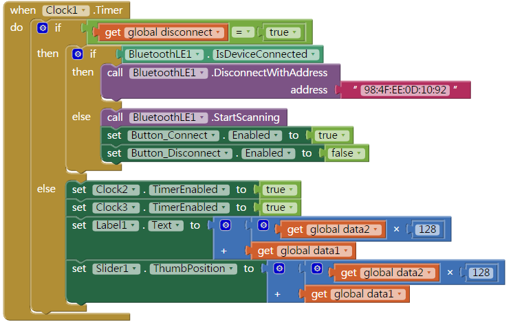
Clock1 元件首先會根據 disconnect 變數值(true/false) 來得知現在是否有與指定 Arduino 101 連線了。如果為 true,則接續判斷是否有連線,如果在連線狀況下就斷線(BluetoothLE.DisconnectWithAddress)。反之則開始掃描 (BluetoothLE.StartScanning)
如果 disconnect 變數值為 false,則開始進行本範例最重要的變數值組合,需要先把 Clock2 與 Clock3 兩個計時器事件啟動。
這是因為 Arduino 類比腳位數值範圍為 0~1023,所以會用到 data2 與 data1 兩個變數值組合起來就是實際的類比腳位數值了,最後呈現在 Label 與 Slider 上就完工囉!
4. Clock2(每0.9秒呼叫一次):
Clock2 會每 0.9 秒把自己與 Clock3 的 Timer事件關閉,接著再根據實際狀況 (就是 disconnect 變數值) 來啟動。

5. Clock3(每0.005秒呼叫一次):控制offset 並組合資料
Clock3 首先會根據 status 變數值 (0, 1) 來控制如何從 Arduino 101 讀取整數(BluetoothLE.ReadIntValue)。接著把 data 變數設為 BluetoothLE.IntGattValue 之讀取結果,如果 data 變數值介於128~256之間的話,就減去 128 後丟給 data2。
如果data 變數值小於 128,則把 data變數值丟給 data1,以便在 Clock1 中進行組合。
請注意 service_uuid 與 characteristic_uuid 這兩個欄位請都填入“19B10011-E8F2-537E-4F6C-D104768A1214”,Arduino 101 都使用這個參數代表它所提供的 BLE 服務。

6. 斷線
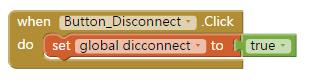
Button_Disconnect按下時,要求BluetoothLE1元件對指定藍牙裝置斷線。在此的做法與先前不太一樣,您可以多多比較喔
Arduino 101 程式碼
本草稿碼請直接複製後上傳至 Arduino 101 即可。請注意 Arduino 101 已經具備藍牙4.0,因此不必再外接 HC05 這類的藍牙裝置
文中一樣要寫明 service_uuid 與 characteristic_uuid,在此都是“19B10011-E8F2-537E-4F6C-D104768A1214”。


請問一下APP INVENTOR一定要使用Arduino 101 才能連接藍芽4.0嗎?
可以使用Arduino MEGA板外接藍芽模組嗎?
Arduino 101 板子本身就有 BLE, 其他Arduino Uno這類的基礎板當然可以另外接BLE module, 這與 App Inventor 無關喔
請問一下:
我怎麼找不到BluetoothLE.IntGattValue 在那裡 ?
請用 ble-test.appinventor.mit.edu 這個站即可,MIT 的 BLE 元件還在修正當中,速度有點慢請見諒
你好 請問有BluetoothLE的函式說明嗎? 我找不到各個功能的說明
您好,其實這個元件MIT還不算正式發佈,您在Blocks頁面把滑鼠移到BLE各指令上會跳出英文說明,我們也是看這個做的。中文說明還要等等喔
你好,我是大陆的电子爱好者,我最近也在了解AppInventor2和Arduino BLE的程序。但是我遇到一个问题是现在最新的AppInventor2 BluetoothLE插件,我没有找到如何可以在app查看服务的特征值,可以帮忙看看吗??O(∩_∩)O谢谢~~
您好,不太懂您的意思? 特徵值不是我們自行指定給Arduino的嘛?
阿吉老師,我曾上過您的課,收獲很多!請問您,這個App inventor 程式是完整的嗎? Timer 1 ,1 秒,Timer2 0 .9秒是在那裡設定,App inventor 程式沒看到設定。
還有,請問老師問什麼要用Timer做接收? 而且要用3個Timer? 謝謝!
程式是完整的喔。三個 timer 各有用途,看一下 code 就可以理解。Timerinterval 是在 Designer 頁面各自的 properties 欄位(畫面最右側) 設定,當然也可以動態用指令來調整。
想請問如果想一次接收多筆類比訊號是可行的嗎?
這部分APP該怎麼寫
另外想請問global的宣告是怎麼宣告呢?
找了許久都找不到
麻煩您了
理論上可行,但也會有上限就是了,這與藍牙傳輸速率與 buffer 有關。宣告 Global variable 請到 App Inventor 的 Blocks頁面左上方 / Variable 即可找到,變數名稱自行修改即可